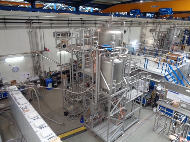
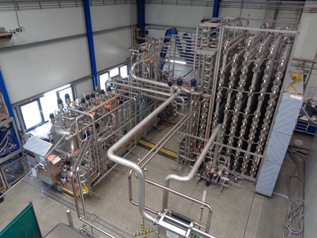
NEVER INSTALLED! CONSTRUCTED TO MEET 3A STANDARDS! CAPABLE OF PROCESSING 7,900 GPH!
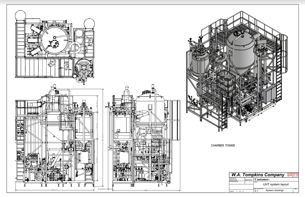
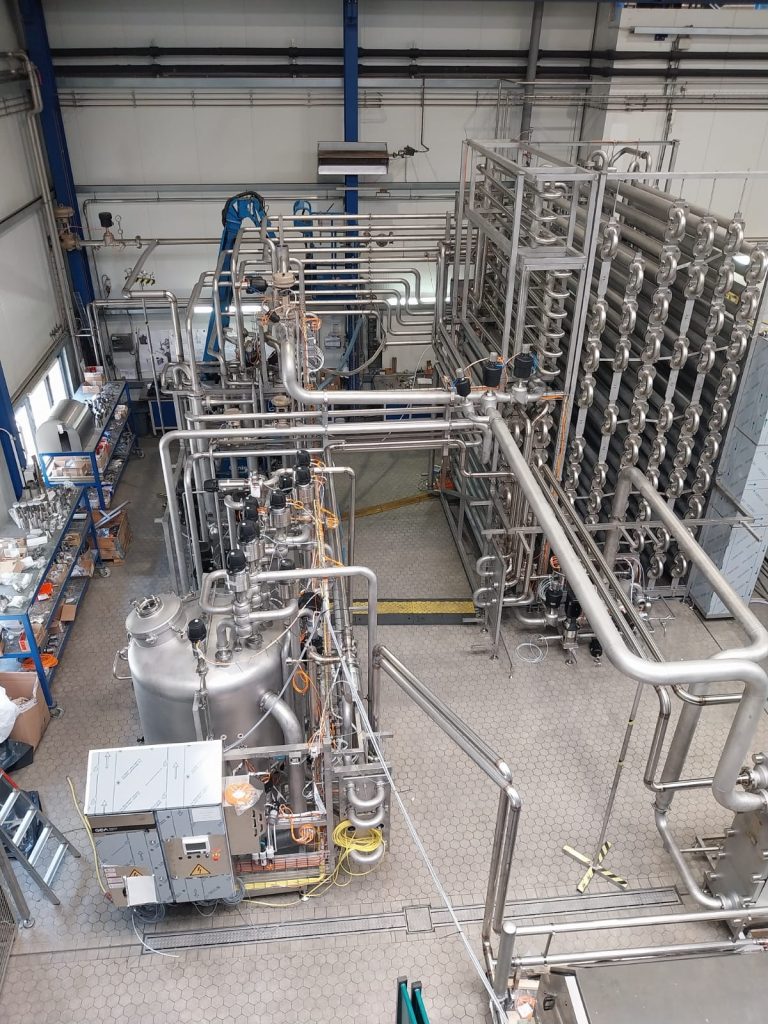
4.12 UHT – ONE (1) FLEXIBLE ASEPTIC PROCESSING PLANT
GEA Indirect and Direct Infusion (UHT) Heat Treatment
Capacity: 30,000 lph (7,925 Gallons) per hour (for Design Products)
Operating Platform
Consisting of:
- 1 Basic rack made of rectangular tube (material SS304) with ball feet to integrate the following components. Variant from the indicated material, equivalent or superior material can be used.
- 1 Balance tank
- Round, closed, and in standing execution with manhole (300 mm) and conical outlet
- Volume 700 liter
- Equipped with a spray ball for CIP and level monitoring
- A special valve combination avoids mixing of product and water during start and stop of production.
- 1 Expansion vessel for closed water circulation
- 1 Screw pump as product displacement pump. The pump is equipped with a frequency converter.
- 1 Centrifugal pump for water circulation. The pump is equipped with a frequency converter.
- 1 Set of valves, ball valves, fittings and accessories Tubular heat exchanger system – For Direct System
- Heating system for the product of 43°F to 176°F by heat exchange with circulating water in counter flow.
- Heating system for the circulating water by heat exchange with saturated steam in counter flow.
- Cooling system for the product of approx. 174°F to 63°F by heat exchange with recirculating water in counter flow.
- Cooling system for the circulating water by heat exchange with chilled water in counter flow.
- Cooling system for the product of approx. 63°F to 37.5°F by heat exchange with glycol (max 28°F) in counter flow.
One (1) Heat holder of tube, for approx. 30 seconds holding time at about 176°F heat-holding temperature. It is possible to bypass the heat holder. The position of the coupling bend is monitored by proximity switches.
Tubular heat exchanger system – For Indirect System
UHT
- Heating system for the product of 43°F to 253°F by regenerative heat exchange with water with inlet to homogenizer at 167°F and heat holder at 194°F.
- Heating system from 253°F to 284°F by heat exchange with hot water.
- Cooling system from 284°F to 93°F by regenerative heat exchange and and inlet and outlet to the homogenizer at approx. 167°F (when homogenizer is connected in Aseptic mode – downstream).
- Cooling system for the product of approx. 93°F to 37.5°F by heat exchange with glycol (max 28°F) in counter flow.
- Heating system for hot water circuit: The hot water is heated to required temperature by heat exchange with steam.
- Cooling system for regenerative circuit. The water is cooled, if necessary, by heat exchange with cooling water before it enters re-cooling system so that product temperature at outlet is kept below the adjusted maximum even after long production hours. The cooling water is fed by regulating valve. The cooling system is heating by steam during sterilization of the system to minimize heat up times.
Heat holder tube for approx. 120 seconds hold time (at 30,000 lph) at about 194-203°F for stabilization of whey protein before heat shock.
Tubular heat exchanger system – For Indirect System
Pasteurizer mode
- Heating system for the product of 43°F to 131°F by regenerative heat exchange with water and with inlet and outlet to the homogenizer at approx. 167°F
- Heating system from 131°F to 176°F by heat exchange with hot water.
- Heat holder of 15 Seconds at 30,000 lph at 176F using flow plates
- Cooling system from 176°F to 93°F by regenerative heat exchange
- Cooling system for the product of approx. 93°F to 37.5°F by heat exchange with glycol (max 28°F) in counter flow.
- Heating system for hot water circuit: The hot water is heated to required temperature by heat exchange with steam.
- Cooling system for regenerative circuit. The water is cooled, if necessary, by heat exchange with cooling water before it enters re-cooling system so that product temperature at outlet is kept below the adjusted maximum even after long production hours. The cooling water is fed by regulating valve. The cooling system is heating by steam during sterilization of the system to minimize heat up times.
Switching between UHT and Pasteurizer mode is realized by flow plates monitored by proximity switches for the correct coupling. In Pasteurizer mode a certain surface of the high heating section is bypassed to reduce the residence time of the product in the higher temperature areas.
In Pasteurizer Mode no (FDA or PMO) regulations (legal requirements) will be followed.
Plate Heat Exchanger
- For Nutritional Product recipes and Cream a plate heat exchanger is required as final cooler to reach required low temperature of 37.5°F
- The plate heat exchanger can be connected to the system using flow plate when running these recipes
- The Plate heat exchanger is not suitable to be cleaned with short CIP and will be cleaned in main CIP only
4.13 UHT – ONE (1) DIRECT MODULE
Consisting of:
- 1 rack made of rectangular tube (material SS304) with ball feet to integrate the following components. Variant from the indicated material, equivalent or superior material can be used.
- 1 Infuser tank for the direct and abrupt product heating from 176°F to max. 295°F by infusion with “foodstuff suitable” saturated steam. The infuser vessel mixes the steam in a natural rectified product stream.
The product and steam inlets are designed to create a thin hollow hose of product, starting right from entrance point to the bottom of the vessel with steam at both sides of the product. The product has an affinity towards the heating medium (steam), so it can get dispersed randomly in the vessel and easily touch the vessel walls which are overheated. GEA uses 2 streams of steam inside the infusion vessel to manage a consistent and straight flow of product as thin film from top to bottom. The heat transfer is very efficient and no cooling is required for the infusion vessel.
- 1 Specially designed centrifugal pump as product displacement pump for the infusor vessel. This pump also keeps the hold tube pressurized. The pump is equipped with a frequency converter for capacity regulation.
- Heat holder of DIN 11850 tube for the ESL production will designed as short as possible (approx. 1 second)
- Heat holder of DIN 11850 tube for 2 second
- Heat holder of DIN 11850 tube for 4 second
- 1 Vacuum de-aerator / Flash Vessel
- For flash cooling of product from max. 295°F to min. 174°F by vacuum and steam condensation.
- The cleaning is executed using spray balls. A centrifugal pump, a valve connection for the cleaning of the flash vessel is realized at a higher capacity in circulation and includes the product side of the steam condensers. For the reduction of the sound level of the vacuum pump, an additional condensate cooler is included in the scope.
- Level control of the product in the flash vessel is measured by a differential pressure transmitters for capacity regulation of the aseptic homogenizer.
- The flash vessel and condensers are sterilized together with the rest of equipment. The flash vessel has condensate barriers for the sight glass and other instruments.
- 1 Aseptic centrifugal pump for product displacement out of the deaerator. The pump is equipped with a frequency converter.
- 1 Vacuum pump to maintain the required vacuum in the flash vessel.
- 1 Set of valves, ball valves, fittings and accessories.
Measurement and Control Devices
- Capacity control for the product
- Capacity control for the water circulation
- Conductance probes to control the concentration of cleaning agents
- Temperature control for the pre-heating temperature
- Temperature control, results from the ratio of the two controlled steam for the infuser
- Atomized product gap regulation of the infuser gap
- Temperature control for the de-aeration outlet temperature
- Temperature control for the outlet temperature
- Temperature control for the filling temperature
- Differential pressure control for product to service media
- Pressure control for the product inlet to the infuser receptacle
- Pressure controls for the steam flows
- Pressure control for the product inlet to the vacuum deaerator
- Mercury thermometer
- Dart temperature sensor
- Recorder Memo-graph
Steam preparation
For the production of saturated culinary steam which is suitable for food
Consisting of:
- Filter system (1 micron)
- Steam dryer
Requirements from customer
- Piping from steam generator to the direct UHT system should made of AISI 304 or superior material
- Steam should be pre-filtered with 25 micron filter.
- Steam feed water preparation has to meet the guide lines “food stuff suitable saturated steam”.
Dosing station for the cleaning concentrates
Installed on a rack (material SS304), for the dosing of acid and caustic concentrates
consisting of:
1 Membrane pump for acid concentrate
1 Membrane pump for caustic concentrate
Lot of Valves, ball valves and accessories
CIP and Sterilization
Main CIP
Dependent on the product and status of the UHT, the operator can select “Main cleaning” or “Aseptic cleaning”.
Some of major steps of Main cleaning are as following:
- Stop production
- Water rinse
- Lye step with NaOH for approx. 30 min at about 281°F
- Waster rinse
- Acid step with HNO3 for approx. 20 min at about 176°F
- Final waster rinse
- Total time for the CIP is about 2.0 hours for indirect and 2.25 hours for direct mode
Aseptic CIP
- Stop production
- Water rinse
- Lye step with NaOH for approx. 30 min at Product temperature
- Waster rinse
- Acid step with HNO3 for approx. 10 min at Product temperature
- Final waster rinse
- Total time for the CIP is about 1.5 hours for indirect and 1.75 hours for direct mode
Sterilization
- 30 min at minimum 277°F
- Total time for the sterilization including heating up and cooling down is about 1.75 hours for indirect and 2.25 hours for direct mode
Control cabinets
Equipped with air conditioning unit
Execution according to UL with labeling
Equipped with assembly plates, on which the following devices are mounted:
- PLC, type Allen Bradley Control Logix safety PLC
- Ethernet Module, Control Logix
- Power section (protective motor switch, contractors)
- Power pack, fuses, clamping rails, etc.
- Pneumatic equipment
- Compressed air supply unit
The following components are installed in the front door of the control cabinet:
- Multichannel-line-recorder
- Panel
The control cabinet is completely pre-mounted and tested.
The following programs are realized by the PLC:
- Sterilization of the plant
- Production
- Production interruption
- Cleaning
The following is signaled as an alarm:
- Lack of product
- High heating temperature not reached
- Compressed air pressure drop
- High system pressure
- High conductivity during production
- Fault indication homogenizer / pump
Double feedbacks by means of ASI Bus
1 Power cabinet / MCC
With air conditioning device
Inside equipped with installation plates, on which the following devices are installed:
- Power section (motor protective switch, contractors, frequency converter from Rockwell PowerFlex 753/755)
- Power pack
- UL Standard and labeling
1 Legal PLC cabinet
A legal panel will be supplied with UHT for ESL application to fulfill PMO requirements.
Pre-assembling
- The complete UHT plant is installed on a stainless steel rack (material SS304) ready for electrical, pneumatic and mechanical connection.
- All parts which are in contact with the product and the service side of the heat exchangers are made of material type AISI 316
- The tubular heat exchangers are sealed with rings made of material PEEK and PTFE.
- The outside of all tubular heat exchangers, frame constructions and tubing are treated with synthetic mineral blasting shots in a compressed air blasting process.
- The machine / the pressure unit is manufactured and tested according to the valid guidelines
- The pressure approved components are based on ASME.
- All heat exchangers are according to 3A
- Feed balance tank, infusion vessel, flash vessel, pumps are according to 3A
- Product pipes will not be certified by 3A but they will be in accordance with 3A requirements.
- The holding tube will be with a slope of min. 2% upwards.
- The tubular heat exchanger and product pipes will not be automatically drainable but drainable by removing the 180° bends and flange connections.